
312-5BE23 - CPUs | CPUs STEP7 programmable, class C
Order no. |
312-5BE23 |
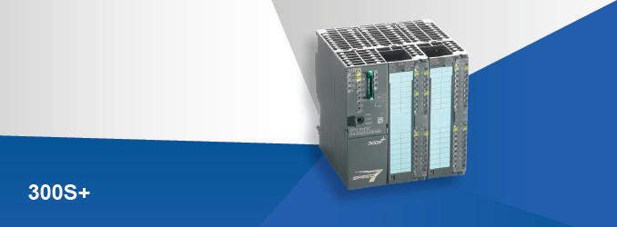
| Type | VIPA CPU 312SC |
General information |
|
| Note | - |
| Features |
Powered by SPEED7 Work memory [KB]: 128...1.024 Onboard 16x DI / 8x DO / 2x Counter / 2x PWM Interface [RJ45]: Ethernet PG/OP communication Interface [2x RS485]: MPI, PtP: ASCII, STX/ETX, 3964(R), USS master, Modbus master/slave Including front connector SD/MMC card slot with locking, up to 8 modules stackable, programmable with WinPLC7, SIMATIC Manager and TIA Portal |
| SPEED-Bus | - |
Technical data power supply |
|
| Power supply (rated value) | DC 24 V |
| Power supply (permitted range) | DC 20.4...28.8 V |
| Reverse polarity protection | |
| Current consumption (no-load operation) | 135 mA |
| Current consumption (rated value) | 500 mA |
| Inrush current | 11 A |
| I²t | 0.7 A²s |
| Max. current drain at backplane bus | 3 A |
| Max. current drain load supply | - |
| Power loss | 8 W |
Technical data digital inputs |
|
| Number of inputs | 16 |
| Cable length, shielded | 1000 m |
| Cable length, unshielded | 600 m |
| Rated load voltage | DC 24 V |
| Reverse polarity protection of rated load voltage | |
| Current consumption from load voltage L+ (without load) | 70 mA |
| Rated value | DC 24 V |
| Input voltage for signal "0" | DC 0...5 V |
| Input voltage for signal "1" | DC 15...28.8 V |
| Input voltage hysteresis | - |
| Signal logic input | Sinking input |
| Frequency range | - |
| Input resistance | - |
| Input current for signal "1" | 6 mA |
| Connection of Two-Wire-BEROs possible | |
| Max. permissible BERO quiescent current | 1.5 mA |
| Input delay of "0" to "1" | 0.1 / 0.35 ms |
| Input delay of "1" to "0" | 0.1 / 0.35 ms |
| Number of simultaneously utilizable inputs horizontal configuration | 16 |
| Number of simultaneously utilizable inputs vertical configuration | 16 |
| Input characteristic curve | IEC 61131-2, type 1 |
| Initial data size | 2 Byte |
Technical data digital outputs |
|
| Number of outputs | 8 |
| Cable length, shielded | 1000 m |
| Cable length, unshielded | 600 m |
| Rated load voltage | DC 24 V |
| Reverse polarity protection of rated load voltage | - |
| Current consumption from load voltage L+ (without load) | 100 mA |
| Total current per group, horizontal configuration, 40°C | 3 A |
| Total current per group, horizontal configuration, 60°C | 2 A |
| Total current per group, vertical configuration | 2 A |
| Output voltage signal "1" at min. current | L+ (-0.8 V) |
| Output voltage signal "1" at max. current | L+ (-0.8 V) |
| Output current at signal "1", rated value | 0.5 A |
| Signal logic output | Sourcing output |
| Output current, permitted range to 40°C | 5 mA to 0.6 A |
| Output current, permitted range to 60°C | 5 mA to 0.6 A |
| Output current at signal "0" max. (residual current) | 0.5 mA |
| Output delay of "0" to "1" | 100 µs |
| Output delay of "1" to "0" | 100 µs |
| Minimum load current | - |
| Lamp load | 5 W |
| Parallel switching of outputs for redundant control of a load | possible |
| Parallel switching of outputs for increased power | not possible |
| Actuation of digital input | |
| Switching frequency with resistive load | max. 2.5 kHz |
| Switching frequency with inductive load | max. 0.5 Hz |
| Switching frequency on lamp load | max. 2.5 kHz |
| Internal limitation of inductive shut-off voltage | L+ (-52 V) |
| Short-circuit protection of output | yes, electronic |
| Trigger level | 1 A |
| Number of operating cycle of relay outputs | - |
| Switching capacity of contacts | - |
| Output data size | 1 Byte |
Technical data analog inputs |
|
| Number of inputs | - |
| Cable length, shielded | - |
| Rated load voltage | - |
| Reverse polarity protection of rated load voltage | - |
| Current consumption from load voltage L+ (without load) | - |
| Voltage inputs | - |
| Min. input resistance (voltage range) | - |
| Input voltage ranges | - |
| Operational limit of voltage ranges | - |
| Operational limit of voltage ranges with SFU | - |
| Basic error limit voltage ranges | - |
| Basic error limit voltage ranges with SFU | - |
| Destruction limit voltage | - |
| Current inputs | - |
| Max. input resistance (current range) | - |
| Input current ranges | - |
| Operational limit of current ranges | - |
| Operational limit of current ranges with SFU | - |
| Basic error limit current ranges | - |
| Radical error limit current ranges with SFU | - |
| Destruction limit current inputs (electrical current) | - |
| Destruction limit current inputs (voltage) | - |
| Resistance inputs | - |
| Resistance ranges | - |
| Operational limit of resistor ranges | - |
| Operational limit of resistor ranges with SFU | - |
| Basic error limit | - |
| Basic error limit with SFU | - |
| Destruction limit resistance inputs | - |
| Resistance thermometer inputs | - |
| Resistance thermometer ranges | - |
| Operational limit of resistance thermometer ranges | - |
| Operational limit of resistance thermometer ranges with SFU | - |
| Basic error limit thermoresistor ranges | - |
| Basic error limit thermoresistor ranges with SFU | - |
| Destruction limit resistance thermometer inputs | - |
| Thermocouple inputs | - |
| Thermocouple ranges | - |
| Operational limit of thermocouple ranges | - |
| Operational limit of thermocouple ranges with SFU | - |
| Basic error limit thermoelement ranges | - |
| Basic error limit thermoelement ranges with SFU | - |
| Destruction limit thermocouple inputs | - |
| Programmable temperature compensation | - |
| External temperature compensation | - |
| Internal temperature compensation | - |
| Technical unit of temperature measurement | - |
| Resolution in bit | - |
| Measurement principle | - |
| Basic conversion time | - |
| Noise suppression for frequency | - |
| Initial data size | - |
Technical data analog outputs |
|
| Number of outputs | - |
| Cable length, shielded | - |
| Rated load voltage | - |
| Reverse polarity protection of rated load voltage | - |
| Current consumption from load voltage L+ (without load) | - |
| Voltage output short-circuit protection | - |
| Voltage outputs | - |
| Min. load resistance (voltage range) | - |
| Max. capacitive load (current range) | - |
| Max. inductive load (current range) | - |
| Output voltage ranges | - |
| Operational limit of voltage ranges | - |
| Basic error limit voltage ranges with SFU | - |
| Destruction limit against external applied voltage | - |
| Current outputs | - |
| Max. in load resistance (current range) | - |
| Max. inductive load (current range) | - |
| Typ. open circuit voltage current output | - |
| Output current ranges | - |
| Operational limit of current ranges | - |
| Radical error limit current ranges with SFU | - |
| Destruction limit against external applied voltage | - |
| Settling time for ohmic load | - |
| Settling time for capacitive load | - |
| Settling time for inductive load | - |
| Resolution in bit | - |
| Conversion time | - |
| Substitute value can be applied | - |
| Output data size | - |
Technical data counters |
|
| Number of counters | 2 |
| Counter width | 32 Bit |
| Maximum input frequency | 10 kHz |
| Maximum count frequency | 10 kHz |
| Mode incremental encoder | |
| Mode pulse / direction | |
| Mode pulse | |
| Mode frequency counter | |
| Mode period measurement | |
| Gate input available | |
| Latch input available | |
| Reset input available | - |
| Counter output available | |
|
| |
VIPA CPU 312SC 312-5BE23
- Brand: Yaskawa
- Product Code: 3125BE23
- Availability: In Stock
-
$0.00
- Ex Tax: $0.00
Tags: VIPA CPU 312SC, 312-5BE23